

Friday, April 17, 2015
Courses Offered
Bachelor Of Technology (B.Tech) Programme
We provide B.Tech Degree in various fields as mentioned below:
> Information Technology
> Mechanical Engineering
> Civil Engineering
> Electronics & Communication Engineering
> Computer Science & Engineering
> Electrical Engineering
Duration: Eight Semesters
Programme Mode: Regular
Eligibility Criteria For B.Tech (1st Year)
Candidate who has cleared 10+2 examination with Physics & Mathematics as compulsory subjects and any of the following optional subjects:
Chemistry/Biology/Computer Science/Biotechnology
Preference criteria for Management Quota seats:
Bachelor Of Technology (B.Tech) Programme
We provide B.Tech Degree in various fields as mentioned below:
> Information Technology
> Mechanical Engineering
> Civil Engineering
> Electronics & Communication Engineering
> Computer Science & Engineering
> Electrical Engineering
Duration: Eight Semesters
Programme Mode: Regular
Eligibility Criteria For B.Tech (1st Year)
Candidate who has cleared 10+2 examination with Physics & Mathematics as compulsory subjects and any of the following optional subjects:
Chemistry/Biology/Computer Science/Biotechnology
Preference criteria for Management Quota seats:
- JEE(Joint Entrance Examination)
- 10+2 Marks
Those candidates who have passed 3 year diploma in engineering or B.Sc (Non-Medical) from any recognized institutions.
Master of Technology (M.Tech) Programme
BFGI offers a full time two-year Post Graduate Programme in Engineering in various fields as following:
> Electronics & Communication Engineering
> Computer Science & Engineering
Duration: Four Semesters
Programme Mode: Regular
Eligibility Criteria
B.Tech or equivalent degree from any recognised university.
Preference criteria for Management Quota seats:
- GATE score
- B.Tech Marks
For more Details: 9501115524, 9501115511, 9501115446, 9501115522

Tuesday, March 17, 2015
AIR ENGINE by Mechanical Engineering, BFCET
It
is a moment of pride for BFCET as its students got third position in a
technical event ‘Techldeate 2015’ held at Manipal university, Jaipur. A total
of 42 teams participated in the event.

All the students are from Mechanical
Department and are in 4th semester. Name of students is Babaldeep
Singh, Gurbhinder Singh, Arjinder Singh, Jaspal Singh. The students while
expressing their happiness thanked their project guide Er. Anoop Monga. HOD
Mechanical, Er. Ajay Sidana appreciated the students and acknowledged the effort
and hard work behind their success.
Wednesday, March 11, 2015
Expert Lecture on the topic “COMPUTER AIDED DESIG AND DRAFTING”
Department of Mechanical Engineering and Civil engineering, BFCET
organized an expert lecture on the topic “COMPUTER AIDED DESIG AND DRAFTING” on
10th March 2014. The lectured was delivered by Er. Arvind Kumar.

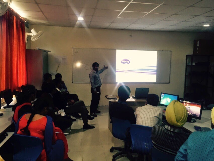
Students of B.tech (ME and CIVIL) 4th semester attended the
lecture. The lecture started at 10: 30
am and lasted till 1:00 pm. The expert motivated the students to strengthen the
basic fundamentals of their respective fields and also to correlate with other
engineering disciplines. He laid emphasis on multidisciplinary approach.
Initially a brief introduction to various design software such as Auto CADD and
Solid works was given and students were motivated to learn and use these design
software. Afterwards, various the widely used commands in Auto CADD and Solid
works were discussed and elaborated by the expert. Finally, the queries of
students were addressed.


Wednesday, October 29, 2014

Wednesday, October 01, 2014
Expert Lecture on the topic “STATE OF ART IN IC ENGINES” on 1st October 2014
Department of Mechanical engineering, BFCET organized an expert lecture
on the topic “STATE OF ART IN IC ENGINES” on 1st October 2014. The
lectured was delivered by Mr. Krishan Kumar. Mr. Kumar is Deputy Manager of
Research and Development in Maruti Suzuki, Gurgoan.
Students of B.tech ( ME) 5th semester and 7th
semester attended the lecture. The
lecture started at 11: 00 am and lasted till 1:00 pm. During the first half,
the expert covered various important aspects of vehicle assembly and engine
assembly. During the second half various topics such as fuel injection, turbo
charging and Super Charging in IC were presented. The final session was an
interaction session which lasted for 30 minutes. Queries of the students were
addressed by the expert in a friendly and comprehensive manner.
Er. Ajay Sidana , HOD Mechanical Engineering expressed
his gratitude to Mr. Kumar for providing the students with an enriching experience.
Also he expressed his thanks to management for providing support for such extra
events.


Thursday, August 14, 2014


Thursday, July 24, 2014

Six-stroke engine
It is a type of internal combustion engine based on the four-stroke engine, but with additional complexity intended to make it more efficient and reduce emissions. Two types of six-stroke engine have been developed since the 1990s:
In the first approach, the engine captures the heat lost from the four-stroke Otto cycle
or Diesel cycle

and uses it to power an additional power and exhaust stroke of the piston in the same cylinder. Designs use either steam or air as the working fluid for the additional power stroke. The pistons in this type of six-stroke engine go up and down three times for each injection of fuel. There are two power strokes: one with fuel, the other with steam or air.
The second approach to the six-stroke engine uses a second opposed piston
in each cylinder that moves at half the cyclical rate of the main piston, thus giving six piston movements per cycle. Functionally, the second piston replaces the valve mechanism of a conventional engine but also increases thecompression ratio.
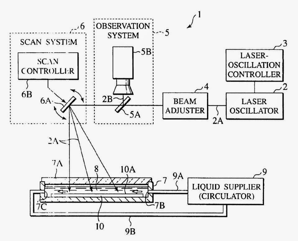
Laser Beam Machining (LBM)
It removes, melts, or thermally modifies a material by focusing a coherent beam of monochromatic light on the workpiece. The LBM process does not involve mass material removal, but does provide rapid material removal with an easily controlled, non-contact, nonwearing tool. The LBM process also places minimal demands on workpiece fixturing in cutting operations and performs a variety of other metal processing functions such as drilling, welding, marking, and heat treating. The effectiveness of LBM in a particular application depends on the pulsing and focusing of the beam and on the reflectivity, absorption coefficient, thermal conductivity, specific heat, and heat of vaporization of the workpiece. The greatest use of lasers is in metal cutting, primarily two-axis profiling of sheet goods that might otherwise have been blanked out by punch press or fabricated by hand after laborious layout of the pattern. Currently, most metal cutting falls within 9.5 mm (0.375 in.) and thinner, although CO 2 lasers are now competitive with plasma arc cutting for metal thicknesses of 13 mm (0.500 in.) and greater. The principal factor in the use of laser metal cutting is manufacturing methodology. Laser cutting is ideal for batch processes, just-in-time, or low-to-medium volume production. Most laser-cutting work is performed on generic or multipurpose material handling systems, as opposed to dedicated automation controlled systems. Generally, there is a clear-cut reason for using one type of laser over another.

Carbon dioxide lasers are capable of delivering much higher average power than Nd:YAG lasers. As such, CO2 lasers can cut faster and produce deeper weld penetration than Nd:YAG lasers. Pulsed Nd:YAG lasers develop a high pulse energy that allows percussion drilling and the cutting of metals at angles and thicknesses not possible with CO2 lasers. There are some applications—spot welding and hole cutting, for example—where either laser type can provide acceptable results at comparable speeds. Capabilities and operating ranges for CO2 and Nd:YAG lasers are shown in Tables and . Laser welding is becoming increasingly used in both low-volume specialty production and high-volume assembly operations. Laser welding operations are typically more dependent on lengthy process development than are cutting applications. Often parts are specifically designed to be laser welded. Laser welding generally requires more precise part fit-up than arc welding processes. While most laser welding is autogenous, that is, without added filler metal, it is becoming apparent that the addition of filler metal to bridge gaps or to act as a buffer when joining metals has great potential.
Water Jet Cutting
A water jet cutter, also known as a water jet or waterjet, is an industrial tool capable of cutting a wide variety of materials using a very high-pressure jet of water, or a mixture of water and an abrasive substance. The term abrasivejet refers specifically to the use of a mixture of water and abrasive to cut hard materials such as metal or granite, while the terms pure waterjet and water-only cutting refer to waterjet cutting without the use of added abrasives, often used for softer materials such as wood or rubber.

Stress-strain diagram for ductile materials
Ductile materials, which includes structural steel, as well as many alloys of other metals, are characterized by their ability to yield at normal temperatures.
Low carbon steel generally exhibits a very linear stress–strain relationship up to a well defined yield point . The linear portion of the curve is the elastic region and the slope is the modulus of elasticity or Young's Modulus. After the yield point, the curve typically decreases slightly because of dislocations escaping from Cottrell atmospheres. As deformation continues, the stress increases on account of strain hardening until it reaches the ultimate strength. Until this point, the cross-sectional area decreases uniformly because of Poisson contractions. The actual rupture point is in the same vertical line as the visual rupture point.

However, beyond this point a neck forms where the local cross-sectional area decreases more quickly than the rest of the sample resulting in an increase in the true stress, On an engineering stress–strain curve this is seen as a decrease in the apparent stress. However if the curve is plotted in terms of true stress and true strain the stress will continue to rise until failure. Eventually the neck becomes unstable and the specimen ruptures (fractures).
Less ductile materials such as aluminum and medium to high carbon steels do not have a well-defined yield point.There are generally two types of yield points,upper and lower yield point. For these materials the yield strength is typically determined by the "offset yield method", by which a line is drawn parallel to the linear elastic portion of the curve and intersecting the abscissa at some arbitrary value (generally from 0.1% to 0.2%). The intersection of this line and the stress–strain curve is reported as the yield point. The elastic region is the portion of the curve where the material will return to its original shape if the load is removed. The plastic region is the portion where some permanent deformation will occur, even if the load is removed. Failure point is when the object ruptures.
Low carbon steel generally exhibits a very linear stress–strain relationship up to a well defined yield point . The linear portion of the curve is the elastic region and the slope is the modulus of elasticity or Young's Modulus. After the yield point, the curve typically decreases slightly because of dislocations escaping from Cottrell atmospheres. As deformation continues, the stress increases on account of strain hardening until it reaches the ultimate strength. Until this point, the cross-sectional area decreases uniformly because of Poisson contractions. The actual rupture point is in the same vertical line as the visual rupture point.
However, beyond this point a neck forms where the local cross-sectional area decreases more quickly than the rest of the sample resulting in an increase in the true stress, On an engineering stress–strain curve this is seen as a decrease in the apparent stress. However if the curve is plotted in terms of true stress and true strain the stress will continue to rise until failure. Eventually the neck becomes unstable and the specimen ruptures (fractures).
Less ductile materials such as aluminum and medium to high carbon steels do not have a well-defined yield point.There are generally two types of yield points,upper and lower yield point. For these materials the yield strength is typically determined by the "offset yield method", by which a line is drawn parallel to the linear elastic portion of the curve and intersecting the abscissa at some arbitrary value (generally from 0.1% to 0.2%). The intersection of this line and the stress–strain curve is reported as the yield point. The elastic region is the portion of the curve where the material will return to its original shape if the load is removed. The plastic region is the portion where some permanent deformation will occur, even if the load is removed. Failure point is when the object ruptures.
Subscribe to:
Posts (Atom)